20100212

Card Reader Using Microcontroller

Card Reader Using Microcontroller

Card Reader Using Microcontroller

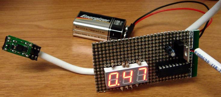
This is a simple version of Card Reader. Why? because this Magnetic Card Reader only in read only environment. It only read the information stored in magnetic card. The purpose of the project is used as card debugger. There are three main part in this project :

  • A reader to capture digital characters from the card
  • A RISC microcontroller to store data and check for errors
  • A display to relay the magstripe contents to the viewer

As processor it use microcontroller AVR ATtiny 2313. For Reader it uses Panasonic ZU-M2121S451 Reader. and for display use LCD 16x2.
"The Magstripe (Track 2) Reader project can be used to view numerics stored a magnetic data card. Although there is no writeback ability, the device is very useful as a card debugger. The treatise will use an LCD character display to relay this data to the user. The circuit uses an AVR microcontroller and can modified to work with similar RISC controllers."
Although the card reader can't write back to magnetic card, I guess this is a one of good reference to learn how card reader work. For download the reference clik here (zip file) or visit this link

Thanks to Brady Mayes for great card reader based on microcontroller.

Digital Camera Interface

Digital Camera InterfaceDigital Camera Interface

How to interface CMOS camera and microcontroller? well, Iñaki Navarro Oiza had made great microcontroller project about it. The camera called c3088 uses a CMOS image sensor OV6620 from Omnivision. To communicate between microcontroller and camera he use I2C protocol. As processor it used Atmel AVR ATmega16.

"The aim of this project is the development and construction of an interface between a CMOS camera and a computer. This interface allows a user to get images from the camera, to change some of the properties of the camera as brightness, luminance, etc from a computer. Also some image process is implemented allowing the camera to track white objects and follow them with a servomotor. The interface was implemented using the Atmel AVR ATmega16 microcontroller."


Download code, schematic, slide and documentation click here

Infrared Remote Control Receiver

Infrared Remote Control ReceiverInfrared Remote Control Receiver

Here is another project from Seradis Vassilis, Infrared Remote Control Receiver. The idea behind the project is how to control Media Center based on PC to switch it On or Of. This project use ATtiny 13 Microcontroller because of its small size and its RAM in case. He use C language to program it. This remote project use RC5 protocol as he said.
For remote control receiver that it could handle both On/Off and windows or program commands you cand use Girder 3.2.9 or PC remote control v4.213. This receiver use RS232 port to communicate with PC at 2400bps.

For more detail about source, schematic and more, you can download here

20100201

Robotic Arm Project


The main objective of this project is to create the virtual representation of a robot’s working environment. This virtual space gives user the ability to test the physical system without ever having to set up the physical environment and also user can practice without having to be on site. Another benefit of using a virtual space is that we can create any representation needed for the user. To control the robot in the real world, as well as the virtual world, we use MATLAB/Simulink to numerically analyze the inverse dynamics of the system. This allows us to specify the robot’s position that we want and then calculate the joint angles that will move the robot to that desired position. The robot will be used to manipulate a set number of objects with known positions within the system, real world or virtual.

Electronic Speed Controller based on PIC microcontroller

This microcontroller project built by Chris Spurlock. He try to make a cheap electronic speed controller for brushed DC motors. All cost for this project only take about $15 and a little more brain power and programming on PIC microcontroller.

I though it's a suitable project for people that want to make a simple electronic project based on PIC microcontroller. Here is the schematic for the project and For more detail information.

AVR Digital Counter


Another cool microcontroller project from jesper. Counter measurer using microcontroller AT 90S2313, you can use ATtiny 2313 to replace it. It could be a simple digital counter count up at 35-40Mhz. The software written in C code.
"It uses only 4 chips - 3 HC TTL's and an Atmel At90S2313 microcontroller. It has a 5 digit LED display plus one used as a band indicator. Even with the LED display, the current consumption is less than 50 mA. It counts up to at least 52 MHz. I couldn't find any signal source in the lab that could supply more than 52 MHz, so it may go a bit higher, but the fClock(typ) for the HC590 is about 35-40 MHz, so you shouldn't really count (no pun intended) on more."

20100124

Graphical LCD Display:


An accurate and simple graphical oscilloscope using a PIC18F2550 microcontroller and an AGM1264F graphical LCD has been constructed using the PIC18F2550 GLCD Text Test as basis. It has the capability of measuring the maximum voltage, peak-to-peak voltage, average voltage, minimum voltage, and the zero-crossing frequency for a DC signal over 100 samples. To capture on rise or fall, the oscilloscope has a built-in edge trigger function that can be set.

Using the change Time Division function, the time scale for the display is variable and can be easily redefined while the voltage range can be changed to 0-5V, 0-2.5V, and 0-1.25V. The relatively slow acquisition time and sampling rate is the main limitations of this oscilloscope due to the fact that the inputs are limited by the constraints of the internal ADC.
A 9V battery is used as the power supply along with a high-accuracy low drop-out linear voltage regulator to provide a stable 5V supply for the microcontroller and the graphical LCD. The power spikes/ripples are prevented by capacitor.

Robot Navigation System


Robot Navigation is a large component of current robotics research. In this paper, a method to implement the “go-to-goal” aspect of navigation is discussed. Specifically, I will first discuss a method called Egocentric Navigation, which was developed at Vanderbilt University’s Center for Intelligent Systems. Then improvements toward making the system more accurate and efficient will be proposed. Finally, the experimental and simulation results of this new Egocentric Navigational system follow. In total, this paper will lay out a complete system for implementation on a robot which will accomplish navigation to goal in a landmark-based “egocentric” manner.

20100119

Fireflies With Small Microcontrollers

This circuit simulates fireflies with small microcontrollers. Here is the circuit and the component used for single fireflies


  1. ATtiny13 microcontroller
  2. Light Dependant Resistor (LDR)
  3. LED
  4. 2 resistors
To make it interesting, assembly it on the board for 25 fireflies. Every single firefly is self contained, there is no over-all controller. Here is the picture

20100117

Interfacing an AVR controller to a GPS Mobile Phone


So my first idea was to combine a microcontroller with a GSM and a GPS modul. There are a lot of these modules over at Sparkfun, for example. Looking through their shop I found the Telit GM862, which is a GSM modul with an built in GPS receiver. That is what I wanted. And they sell great break out boards to make it easier for hobbyist to access these modules.

Here are some of the features of this GSM-GPS module:
  • Quad band GSM
  • 17mA average stand-by, 3.5mA in low-power mode
  • 250mA average operating current
  • SiRF III GPS Receiver Built In
  • Data, Voice, SMS, and Fax
  • Data speeds up to 57.6kbps
  • Supply voltage : 3.4-4.2V
  • CMOS Camera Capable
  • Python Interpreter built-in

Voice means you are not limited to mobile tracker applications. You could attach a speaker and a microphone to build a complete mobile phone!

Ultrasonic Spotlight Tracker

Ultrasonic Spotlight Tracker
The ultrasonic spotlight tracker is a system that uses a wireless beacon to track a target’s location using both RF signals and ultrasound waves. It then drives a light source to point at the location of the target.
In this project, we limit our remote unit’s degree of freedom to two dimensions to prove the concept, although it can be very easily extended to three dimensions. To locate the target, we need to measure the distance of the target from at least two known points. The distances are measured by counting the time it takes for sound to travel from the target to the base station and multiplying it by the speed of sound waves. The speed of sound in air is about 334 meters per second. The 16 MHz microcontroller avr can count time intervals on the order of 0.0625 microseconds, which gives a theoretical accuracy of 0.02 mm.

20100116

Inex Interactive C Robot Kit

High performance C programmed robot kit

For power hungry hobbyists

Perfect for students, or anyone looking for an easy to build robot that is programmed in C

The Inex Interactive C Robot Kit V2.0 includes the AX-11, a 68HC11 based microcontroller board, an assortment of great sensors, 2 DC gearboxes and mechanical parts for building and modifying 8 sample robot projects (see manual below).

The AX-11 microcontroller boardThe AX-11 microcontroller board

The AX-11 microcontroller board is a modified version of the popular Handy board from MIT. The AX-11 is a microcontroller system that is used to run robot design courses and competitions at the university and high school level, build robots for fun, and control industrial devices. This board uses the 68HC11 microcontroller and has 32KB non-volatile RAM, 9-digital inputs , 21-channels 8-bit ADC, 4-DC motor driver, 6-Servo motor driver, a 16x2 LCD module for display and an infrared LED with 38kHz IR module. Data can be downloaded from your PC via its RS-232 port.

The Inex Interactive C Robot Kit is programmed in C. The Interactive C environment consists of a compiler (with interactive command-line compilation and debugging) and a run-time machine language module. It has many functions and libraries to directly support robot programming.

Includes

  • Controlled by 68HC11 Microcontroller
  • 32KB non-volatile RAM
  • Serial port interface
  • LCD 16x2 display
  • Piezo speaker
  • Ability to drive 4-DC motors (2 gearmotors are included)
  • 6-Servo motor ports (servo motors sold separately)
  • 6-Digital inputs
  • 8-Digital outputs
  • 21-Analog inputs
  • 12V Power Supply (included)
  • 6xAA battery holder
  • Sensors (GP2D120 IR ranger, 2 wheel encoders)

This kit comes complete with Thai manuals (English manual can be found below) and CAI software for learning to program the robot. Everything you need to successfully build your robot is provided.

The manual includes instructions on using a SFR04 ultrasonic rangefinder (RB-Dev-01), IR proximity sensors (RB-Lyn-02) and the CMPS03 magnetic compass (RB-Dev-03) which can easily be interfaced with the Interactive C Robot (sold separately). Add any of our sensors and increase its awareness!

20100114

Tempereature Controller using Microcontroller AVR


Tempereature controller made for monitoring temperature and control the heater. This microcontroller project created by jesper.It's based on an Microcontroller AVR AT90S2313 and a Dallas DS1621 Digital Thermometer. The temperature is displayed on a dual 7-segment display, and two buttons are used for setting parameters. A high current relay switches the heating element.

The project use C language to programm it, will make everything more easier. A 4 MHz ceramic resonator is used for clocking the 2313. "A fun little construction and a good way to learn about the DS1621" Jesper said. This could be a good microcontroller project for you who want to learn How to interface DS1621 to Micorocntroller AVR using I2C protocol.

View Schematic and download the project code

20100113

Dot Matrix Scrolling Sign based on Microcontroller AVR


Do you want to learn for Scrolling Dot Matrix Display based on microcontroller? i thought this project will be great for you. The project use Basic language and Bascom AVR to compile it. The processor use At Tiny 2313.
"The Dot Matrix Display has an 5x7 led matrix with 5 columns and 7 rows.The display is controlled by the ATTiny2313 microcontroller. The rows are controlled by PORTB of the microcontroller, while PORTD puts the data on the columns to make the characters. The Dot matrix display used here is the LTR-747HR and is 0.7 inch (17.8mm) high."
View Schematic and download source code (.bas)
note: picture take from tinkerlog photostream. Not related to this project
link

20100112

Interfacing microcontroller avr to GPS mobile phone


There are already mobile tracking devices out there, but they seemed to be too expensive and too closed for my needs. Another option is one of these new Nokia N95 which have built-in GPS. They are really nice, but about 600€, which is not a bargain. So I decided to do my own." alex said

Materials

The first idea was to combine a microcontroller with a GSM and a GPS modul. There are a lot of these modules over at Sparkfun, for example. Finally he choose Telit GM862, which is a GSM modul with an built in GPS receiver. Sparkfun sell great break out boards to make it easier for hobbyist to access these modules.

Here are some of the features of this GSM-GPS module:
  • Quad band GSM
  • 17mA average stand-by, 3.5mA in low-power mode
  • 250mA average operating current
  • SiRF III GPS Receiver Built In
  • Data, Voice, SMS, and Fax
  • Data speeds up to 57.6kbps
  • Supply voltage : 3.4-4.2V
  • CMOS Camera Capable
  • Python Interpreter built-in
Here the link for instruction how to experiment with it step by step.

Tiny AVR Microcontroller Runs on a Fruit Battery

People like lemon because it a delicous fruit. It contains vitamin C and good for our healthy. But, in this posting I don't talk about kind of lemon and i just talk about related between lemon and electronic. What will we talk is about small microcontroller project using Tiny AVR and lemon.
As we know liquid of lemon can be use as electrolyte. Together with copper and zinc as electrode, it can produce amount of current. How much current? Its depends on the surface area of the electrodes in contact with the electrolyte as well as the quality/type of electrolyte. The voltage produce by lemon cell is about 0.9 V.
Although, there is small voltage. It can be used to powered PicoPower AVR microcontrollers. For example Tiny13V is very appropriate for such an experiment, since V type of AVR is rated to work down to 1.8V power supply voltage.


If you don't believe just try by yourself at home. Here the link for instruction how to experiment with it step by step.

20100111

Tutorial : MiniPOV based on microcontroller AVR AT tiny 2313

Did you like electronic project especially related to LED? if you do, then MiniPOV is a great electronic project for you. It's a simple project, but it will amaze you when you finish build it. MiniPOV is one of Persistence of Vision that give eye illution patern when it swinged in the air. This cool project made by Ladyada. This project based on microcontroller AVR ATtiny 2313.

You wanna try to build it. Here is step by step to make cool Mini POV. Just use your imagination to make another great POV

20100110

Battery Low Voltage Beeper

This electronic circuit is an alarm circuit for low battery condition. It provides an audible and visual low voltage warning for 12V battery powered devices. When the battery voltage is above the set point (typically 11V), the circuit is idle. If the battery voltage should fall below the set point, the LED will light and the speaker will emit a periodic beeping sound to warn of the impending loss of power. The circuit was designed for monitoring solar systems, but it could also be useful for automotive and other 12V applications.


How it works
U2 provides a 5V regulated voltage reference. U1 is wired as a comparator, it compares the fixed 5V regulated voltage to the voltage on the wiper of VR1, that is proportional to the 12V supply. When the supply drops below the set point, the output of U1 goes low, turning on Q1 and powering the beeper and the LED.

The beeper consists of U4, a tone generator, and U3, a low duty cycle pulse generator. The tone can be changed by adjusting R7, the beep rate can be changed by adjusting R5. A small amount of hysteresis is provided by R1 and the current through LED1 and the beeper, this separates the on and off points for the circuit.

Use of Battery Low Voltage Beeper
Connect the circuit to the 12V source that you wish to monitor. Turn S1 on, if the battery voltage is above the set point, nothing should happen.

As the battery voltage drops below the set point, the LED will light and a periodic beeping will come from the speaker. If the beeping becomes annoying, turn off S1. Be sure to charge the battery soon, excessive discharging will shorten the life of most rechargeable batteries.

More about Battery Low Voltage Beeper

Parts Lists : Printed Circuit Image (PostScript File) Component Placement Silkscreen (PostScript File)


Car Anti-Theft Wireless Alarm

This alarm circuit is an anti- theft wireless alarm can be used with any vehicle having 6- to 12-volt DC supply system. The mini VHF FM radio-controlled, FM transmitter is fitted in the vehicle at night when it is parked in the car porch or car park.


The receiver unit of the wireless alarm uses an CXA1019, a single IC-based FM radio module, which is freely available in the market at reasonable rate, is kept inside. Receiver is tuned to the transmitter's frequency. When the transmitter is on and the signals are being received by FM radio receiver, no hissing noise is available at the output of receiver. Thus transis- tor T2 (BC548) does not conduct. This results in the relay driver transistor T3 getting its forward base bias via 10k resistor R5 and the relay gets energised.

When an intruder tries to drive the car and takes it a few metres away from the car porch, the radio link betw- een the car (transmitter) and alarm (receiver) is broken. As a result FM radio module gene-rates hissing noise. Hissing AC signals are coupled to relay switching circ- uit via audio transformer. These AC signals are rectified and filtered by diode D1 and capacitor C8, and the resulting positive DC voltage provides a forward bias to transistor T2. Thus transistor T2 conducts, and it pulls the base of relay driver transistor T3 to ground level. The relay thus gets de-activated and the alarm connected via N/C contacts of relay is switched on.

If, by chance, the intruder finds out about the wireless alarm and disconnects the transmitter from battery, still remote alarm remains activated because in the absence of signal, the receiver continues to produce hissing noise at its output. So the burglar alarm is fool-proof and highly reliable. (Ed: You may have some problem catching the thief, though, if he decides to run away with your vehicle_in spite of the alarm!)


Go to Car Anti-Theft Wireless Alarm Forum

20100109

Project on Design of a Biped Robot with Efficient Motion Control


This Project involved construction, design, control and analysis of a Biped Robot. This robot uses the dynamic balancing for the Motion Control. The robot had two legs for walking. The robot was controlled using the 12 FUTABA S3003 servo motors which were controlled in the real time using the serial port programming of Servo motors with the Computer and the Microcontrollers PIC16F84 and PIC16F877.

For Full Project Download


20100108

Controlling AVR with Visual Basic

Controlling AVR with Visual BasicControlling AVR with Visual Basic

The purpose of this microcontroller project is to give the student a figure out about How to Control AVR Devices using Visual Basic (PC). To comunnicate between PC and Microcontrller, it use RS232. So, this is not a stand alone project. From this general microcontroller project the student can improve and made more specific to meet their requirement. This project creted by Serasidis

"The use-range of this application is very high. You can make, anything you want, that its need control from PC computer or some circuit that is collect data from somewere, and at the end, its give this data to PC computer via RS232 port to our software"

NiCd/NiMH Battery Charger

NiCd/NiMH Battery ChargerNiCd/NiMH Battery Charger

Commercial NiCd/NiMH Battery Charger, As you may have noticed, are not that Efficient when it comes to charging time. There might be some expensive models but we are not referring to that. One of the solution is using Intelligent NiCd/NiMH Battery Charger created by Peter Hayles. This Efficient NiCd/NiMH Battery Charger build using microcontroller PIC 16C711. Because it will reduce the complexity of the circuit. He says that with the DIY charger he managed to cut the charging time from 4 hours to 1.5 hours max. This sound good to me.

"This cheap and easy to build NiCd/NiMH Battery Charger is suitable for automatically charging a wide range of batteries for many applications. Proper chargers are usually expensive and cheap chargers supplied with the original equipment often incorrectly charge the cells and dramatically shorten their life. This 'intelligent' charger was designed for high current and rapid charge applications such as cordless power tools and model racing cars."

20100107

Digital Camera Interface

Digital Camera InterfaceDigital Camera Interface

How to interface CMOS camera and microcontroller? well, Iñaki Navarro Oiza had made great microcontroller project about it. The camera called c3088 uses a CMOS image sensor OV6620 from Omnivision. To communicate between microcontroller and camera he use I2C protocol. As processor it used Atmel AVR ATmega16.

"The aim of this project is the development and construction of an interface between a CMOS camera and a computer. This interface allows a user to get images from the camera, to change some of the properties of the camera as brightness, luminance, etc from a computer. Also some image process is implemented allowing the camera to track white objects and follow them with a servomotor. The interface was implemented using the Atmel AVR ATmega16 microcontroller."

Data Acquisition & Logging System

Data Acquisition & Logging SystemData Acquisition & Logging System

This microcontroller project log the temperature system. It can be used to monitoring and controlling environment temperature as we needed. i know that the chip, AT89C51, little out of date, but at least we can still learn the system How to make Data Acquisition & Logging System with microcontroller. This great project made by Abbas Raza

"The status and temperature date saved to PC via serial communication. Here 8 temperature sensors are connected(4 shown in diagram for simplicity). values of all the sensors are sent serially by AT89C51 to pc. Software "DAQ System " takes these values and show them on its front panel, and also logs them to the data base "daq.mdb" .we can set some parameters like set point , low limit ,and high limit . when temperature of some sensor increases beyond set point ,the heater connected to controller (specific for that sensor) will be turned OFF( ON in opposite case ).High limit and low limits are for alarm. when temperature goes above high limit or below low limit the alarm will be turned on."

Wireless Graphic LCD


Today, I was thinking how dirty and full of stuff my desk was. So I decided to relocate my graphic LCD to another person’s desk but still have control over it. To do this, I figured I could simply use the ACODE-300 wireless bluetooth modules.

Required Parts :
  • 2 ACODE-300 Bluetooth modules
  • 1 ACODE Interface Board
  • 2 LEDs
  • 1 LM3940 or any 5-to-3.3v regulator
  • 1 15K and 30K resistors
  • 1 GHLCD graphic LCD (or any serial LCD)
  • 6 4-pin sockets (or simply cut a 16-pin socket like me~)
  • 1 CUBLOC or some type of microcontroller
  • 1 CUBLOC Study Board or some type of microcontroller
You can get ACODE-300, ACODE interface Board, GHLCD graphic LCD, CUBLOC, and Study Board from cubloc.com.
For complete reference, source code, Schematic, you can Schematic Download, PromiWIN4.0_Setup(En).exe Download, Tetris Program Download

DE-ACCM5G Application Note G Meter for your car


The DE-ACCM's buffered outputs are ideal for connection to a microcontroller's analog input pins. In this project I used this functionality to make a simple G meter suitable for mounting into a car. It displayed the amount of acceleration in units of g whenever the car was accelerating or braking. This project is suitable for anyone experienced in developing for an analog enabled microcontroller.

Here’s an article about how to make a G-Meter for your car.
link

20100106

USB AVR Programmer

USB AVR Programmer

Serasidis says "Nowadays, USB is the most popular connection connection between PC and peripherals such as AVR programmers, printers, scanners etc. For that reason I had to modify my old serial AVR In-System-Programmer (ISP) to work with USB connection. You can say, "use a USB to Serial adaptor to connect your AVR ISP with your PC". Yes, that could be a solution but it would cost me more money than a singe FT232BM chip because I had to include an USB to RS232 adaptor and a power supply for my programmer. (almost €30)".

So, the solution was to replace the two transistors, that were used to adapt the RS-232 voltage levels to TTL voltage levels, with a USB to RS-232 chip such as FT-232BM.

Small TV Terminal AVR Project

Small TV Terminal AVR ProjectSmall TV Terminal AVR Project

When you use microcontrollers in your designs, sometime you face a problem how to show user required data. Several LEDs, 7 segment display or LCD module can be solution. But if you must show a lot of information simultaneously, it can be difficulty. Large LCD modules are expensive and graphic modules require complicated control. You can solve it with a help of PC. Just send data via serial line to the computer and display everything on computer's display said Vassilis Serasidis.

Twitter Hack – How to Make a Laser-Trip Webcam Security System!

Here’s a great Twitter Hack that involves Arduino, Linux, webcam, and a laser pointer to make it a complete Twitter Security System! Awesome, this is the best use of Twitter I have seen so far, simple yet effective webcam security system!

"This instructable will show you how to construct a laser tripwire that can twitter and grab an image from a webcam, as well as execute any command you can put in a bash script.
This instructable is actually quite simple and is even suitable as a beginner arduino project. It requires a GNU/linux (or possibly Mac) operating system with the arduino IDE and Processing IDE working properly. This project could also be implemented in Windows if you created a more complex processing application."

DIY Dual Fan Controller Project

DIY Dual Fan Controller Project

Here’s a nice little circuit diagram for all those hardcore DIYers if you are trying to build a dual fan controller using an ATtiny45 although I’d never use this thing, I’d rather use a CUBLOC.

"Over the course of a weekend, I cobbled together some leftover robot parts to create a simple dual-fan controller. The board turns on the first fan when the temperature reaches a user-adjustable dial setting, and it turns on a second fan if the temperature exceeds an additional 5 degrees Fahrenheit. With this method, only a single fan is used if the temperature can be kept under control with only one fan, but both fans will kick on if necessary."

20100105

The Strength of 8-bit

When Renesas was formed in 2003, they took Mitsubishi's successful low-power M16C 16-bit core, added Hitachi's sophisticated peripherals, and created a modern microcontroller that is easy to learn. Targeted towards efficient, low cost applications, this is now one of the most popular 8/16-bit microcontrollers available. This 8-bit Flash microcontroller family is the Renesas R8C.

FEATURES OF THE RENESAS R8C 8-BIT MICROCONTROLLER INCLUDE :
  • Optimized 20MHz R8C CISC Core
  • 8-bit internal data paths with a 16-bit
  • ALUCore data registers configurable as 8-bit, 16-bit, or 32-bit
  • CPU Address Registers configuration: 16-bit or 32-bit configuration
  • Dual data registers for fast context switching - see animation -->
  • Hardware Multiplier performs a 16x16 multiply in 5 cycles
  • Sub 1µA standby mode
  • Entire Flash array is byte-writable
  • Single-Cycle Memory Access
  • Data Transfer Controller (similar to a DMA) provides high-speed data transfer with no CPU intervention
  • Data types: -> Signed or unsigned integer (8-bit) -> Signed or unsigned word (16-bit) -> Signed or unsigned long word (32-bit) -> Packed decimal
  • Vectored interrupts with seven levels of priority
  • One wire on-chip debug with trace, and break on data and address
  • Automotive Grade available
Read more

Embedded Ethernet MiniCore™ from Rabbit!

The RCM5700 Development Kits have that you need to quickly design a very small Embedded Ethernet microprocessor-based system. Choose either a standard or deluxe development kit. Both kits includes RCM5700 microprocessor core module, development board with prototyping area and complete documentation on CD-ROM, and a Getting Started manual. A USB cable is included. The deluxe kit will include power supplies, and additional protyping boards for specific sample programs. Both development kits come with Rabbit's industry-proven Dynamic C integrated development software that includes an editor, compiler, and in-circuit debugger. Programming is easy with hundreds of samples and libraries that can be used as building blocks to your code.

Windmeter using Microcontroller

Windmeter using MicrocontrollerWindmeter using Microcontroller

The Windmeter is an anemometer designed to measure and record wind speed distribution from 0 to 17+ meters per second. It was designed for high reliability, ease of construction, and for a wide environmental range. Data is logged over a period of 30.46 days (1/12 of a year), and then saved for 11 months. The data can be retrieved with a laptop computer any time within the 12 months of logging. The Windmeter is self-powered by a solar pannel and battery. Calibration of the Windmeter can be done against a car's speedometer or better yet a GPS receiver. The Windmeter should cost you under $300 to make.

Flickr Images on A Nokia LCD and AVR

Flickr Images on A Nokia LCD and AVRFlickr Images on A Nokia LCD and AVR

Another electronic project related to LCD. Alex has created microcontroller project : Flickr images on a Nokia LCD. The "brain" used microcontroller AVR ATmega48 and the software, he decided to fetch images from Flickr using Beej’s Python Flickr API.
Is it difficult to bulid this cool microcontroller project? well, if you follow what alex said i'm sure you can do it. May be i'll built it someday

20100104

Data Acquisition & Logging System

Data Acquisition & Logging System Using AT89c51This microcontroller project log the temperature system. It can be used to monitoring and controlling environment temperature as we needed. i know that the chip, AT89C51, little out of date, but at least we can still learn the system How to make Data Acquisition & Logging System with microcontroller. This great project made by Abbas Raza

"The status and temperature date saved to PC via serial communication. Here 8 temperature sensors are connected(4 shown in diagram for simplicity). values of all the sensors are sent serially by AT89C51 to pc. Software "DAQ System " takes these values and show them on its front panel, and also logs them to the data base "daq.mdb" .we can set some parameters like set point , low limit ,and high limit . when temperature of some sensor increases beyond set point ,the heater connected to controller (specific for that sensor) will be turned OFF( ON in opposite case ).High limit and low limits are for alarm. when temperature goes above high limit or below low limit the alarm will be turned on."

For complete reference, source code, Schematic, you can download here.

20100103

NiCd/NiMH Battery Charger

NiCd/NiMH Battery ChargerCommercial NiCd/NiMH Battery Charger, As you may have noticed, are not that Efficient when it comes to charging time. There might be some expensive models but we are not referring to that. One of the solution is using Intelligent NiCd/NiMH Battery Charger created by Peter Hayles. This Efficient NiCd/NiMH Battery Charger build using microcontroller PIC 16C711. Because it will reduce the complexity of the circuit. He says that with the DIY charger he managed to cut the charging time from 4 hours to 1.5 hours max. This sound good to me.

"This cheap and easy to build NiCd/NiMH Battery Charger is suitable for automatically charging a wide range of batteries for many applications. Proper chargers are usually expensive and cheap chargers supplied with the original equipment often incorrectly charge the cells and dramatically shorten their life. This 'intelligent' charger was designed for high current and rapid charge applications such as cordless power tools and model racing cars."
Download for the schematic and document (Zip file), click here.

Controlling AVR with Visual Basic

The purpose of this microcontroller project is to give the student a figure out about How to Control AVR Devices using Visual Basic (PC). To comunnicate between PC and Microcontrller, it use RS232. So, this is not a stand alone project. From this general microcontroller project the student can improve and made more specific to meet their requirement. This project creted by Serasidis

"The use-range of this application is very high. You can make, anything you want, that its need control from PC computer or some circuit that is collect data from somewere, and at the end, its give this data to PC computer via RS232 port to our software"

For VB code, schematic, document you can download here (i've collected them in one zip file)

20100101

TV-B-Gone Project

TV-B-Gone Project
TV-B_Gone is another fun DIY microcontroller project. It's a simple remote control for TV that has function only Turn Off. So, there is only one button, power button. No Longer dumb advertisemsent on your TV, just use this cool microcontroller project to switch it off.

You can get this device on the market. But if you want to build it by yourself there are good news for you. Lady Ada an Mitch has build an open source version of the TV-B-Gone. it means you can download the schematic and the layout based on open source license.

How does it work?
If you hit the button it plays simply every shut down code stored in microcontroller and send it out to IR led. The transistors are used to drive a stronger current through the IR-LEDs. The latest TV-B-Gone kit have a range of about 50 meters. For the power supply you can use two battery AA.

Digital Guitar Tuner

Guitar is one of the most favourite music instrument. To get great sound you need to tune it first. There are many guitar tuner based on electronic circuit that can be use to tune guitar easily. One of them is Digital Guitar Tuner using microcontroller AVR Atmel 2323 created by Jesper.

Digital Guitar Tuner"This microcontroller project is a simple, but accurate for Digital Guitar Tuner. It samples the input, which can be directly from the mics of an electric guitar, or from a microphone, it you're using an acoustic guitar. The circuit also can be used for tuning other instruments."

The samples are then checked against stored values for the strings, and the two LED's will show the tuning status - "Too Low", "Too High" or "In Tune" when both LED's are lit. The tuner will automatically switch between the six strings. The circuit is pretty simple. A small transistor amp pumps up the input signal to something the AVR can see on it's input pin. The other two I/O pins are used for driving the LED's. The input sensivity is around 50-60 mV. This gives a 2-3 V swing on the input pin, enough for the 2323 to read this as high and low levels.

If you interest to build this project, you can download the document, source code, schematic here (zip file)

[link]

Interfacing DRAM Memory with AVR

Interfacing DRAM Memory with AVR
Is it possible to use DRAM with microcontroller AVR? Yes, it is possible. Jesperh has proved it. He hooked up a DRAM to a small processor (in this case an Microcontroller Atmel 8515), and handle the RAS/CAS sequencing and refresh in software. The type of DRAM is Hitatchi M5M44800, a 512k*8 DRAM!. Bigger than the original memory of microcontroller AT90S8515 that is 512 byte RAM. The project use C to programm it. The chip required small power consumption, only takes about 2-3 mA when just refreshing and with a low access rate.

But, the consequency is it will be relatively slow and put some extra load on the CPU, but if you need a cheap, large RAM memory and can accept the overhead, this is the way to go. But, with more bigger memory you get. It would not to bad to try isn't.

If you need source code, schematic, and documentatiaon about this microcontroller project click here (zip).

Another project by jesper
1. AVR digital counter
2. Temperature Controller

[via]