20081123

Mendalami Prosedur dan Fungsi

Dalam penulisan program bahasa C, kadang terdapat program yang kita gunakan berulang-ulang. Dengan metode penulisan secara sederhana kita akan menulisa code tersebut berulang-ulang, hmmm..... pasti merepotkan. Dengan Prosedur dan Fungsi, kita gak perlu repot-repot menulis setiap baris code tersebut.

1. Prosedur

Perhatikan contoh program berikut:

#include<mega8535.h>

#include<delay.h>

void main()

{

DDRA= 0xff;

PORTA=0x00;

while(1)

{

PORTA=0x01<<0;

delay_ms(50);

PORTA=0x01<<1;

delay_ms(50);

PORTA=0x01<<2;

delay_ms(50);

PORTA=0x01<<3;

delay_ms(50);

PORTA=0x01<<4;

delay_ms(50);

PORTA=0x01<<5;

delay_ms(50);

PORTA=0x03<<0;

delay_ms(50);

PORTA=0x03<<1;

delay_ms(50);

PORTA=0x03<<2;

delay_ms(50);

}

}

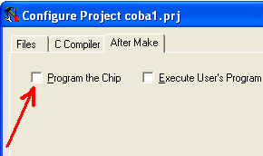
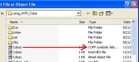
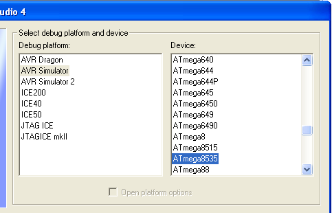
Simulasikan program di atas menggunakan AVR Studio4. Maksud dari code << yaitu untuk menggeser bit ke kiri :

PORTA=0x01<<n; //menggeser nilai sebesar 0x01 digeser ke kiri sebanyak n.

//Dan mengeluarkan hasilnya ke Port A

misal:

PORTA=0x01<<2; //artinya menggeser nilai 0x01 digeser ke kiri sebanyak 2 kali.

//lalu hasilnya dikeluarkan ke Port A

Pahami gambar berikut:

image

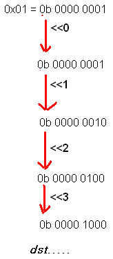
nilai yang dikeluarkan ke Port A, sama seperti gambar di samping.

Pertama, kondisi high pada Port A.0 lalu Port A.1 kemudian Port A.2 dan seterusnya.

Logika yang sama juga digunakan untuk code program berikut:

PORTA=0x03<<n

//nilai digeser ke kiri sebanyak n.

//tapi kali ini nilai yang digeser sebesar 0x03 = 0b000 0011

program di atas dapat juga ditulis seperti dibawah:

#include<mega8535.h>

#include<delay.h>

void geserkiri_A()

{

PORTA=0x01<<0;

delay_ms(50);

PORTA=0x01<<1;

delay_ms(50);

PORTA=0x01<<2;

delay_ms(50);

PORTA=0x01<<3;

delay_ms(50);

PORTA=0x01<<4;

delay_ms(50);

PORTA=0x01<<5;

delay_ms(50);

}

void geserkiri_B()

{

PORTA=0x03<<0;

delay_ms(50);

PORTA=0x03<<1;

delay_ms(50);

PORTA=0x03<<2;

delay_ms(50);

}

void main()

{

DDRA= 0xff;

PORTA=0x00;

while(1)

{

geserkiri_A();

geserkiri_B();

}

}

Pada program di atas, main program hanya berisi beberapa baris program saja. Main program memanggil prosedur geserkiri_A kemudian memanggil prosedur geserkiri_B.

Saat sebuah prosedur dipanggil, maka code program yang berada di dalam prosedur (di dalam kurung kurawal ) akan dijalankan oleh microcontroller. Cara memanggil prosedur cukup dengan menuliskan nama prosedurnya diikuti tanda kurung ( ) . Contoh:

............

............

geserkiri_A();

//berarti micro akan menjalankan code program yang ada di dalam prosedur geserkiri_A()

............

Dengan menggunakan prosedur, main program akan terlihat lebih simple dan mudah dipahami.

2. Fungsi

Fungsi merupakan prosedur yang memiliki nilai return (menghasilkan nilai).

Perhatikan code program berikut:

#include<mega8535.h>

#include<delay.h>

unsigned char baca_PINA()

{

unsigned char d;

d=PINA;

return d;

}

void main()

{

DDRA=0x00;

DDRB=0xff;

while(1)

{

PORTB=baca_PINA();

}

}

Pada contoh program di atas terdapat fungsi baca_PINA.

unsigned char baca_PINA()

{

unsigned char d; //mendeklarasikan variabel d dengan tipe data unsigned char

d=PINA; //memasukkan nilai PINA ke variabel d

return d; //mengembalikan(return) nilai d

//nilai d ini merupakan nilai yg dihasilkan saat fungsi baca_PINA dipanggil

}

Cara memanggil fungsi seperti di atas sama dengan cara memanggil prosedur. Cuman karena fungsi menghasilkan sebuah nilai, maka kita harus menyediakan tempat untuk menampung nilai tersebut. Contohnya pada program di atas terdapat code program berikut:

PORTB=baca_PINA(); //memanggil fungsi baca_PINA ,

//lalu mengeluarkan hasilnya ke PORTB

Mungkin ada temen2 yang tanya, kenapa harus memakai fungsi segala, program untuk membaca nilai PINA lalu mengeluarkannya ke PORTB kan bisa ditulis seperti ini:

...........

..........

while(1)

{

PORTB=PINA;

}

.........

Iya YA... kenapa mesri repot2.. HEhehe..

Program di atas kan hanya contoh simple aja biar gak bingung. Aplikasi sesungguhnya dari penggunaan fungsi adalah saat kita membaca data dari sensor, adc, serial dll...

NB:

Ada prosedur dan fungsi yang membutuhkan nilai masukan. Misal:

unsigned int read_adc(unsigned char adc_input)
{
ADMUX=adc_input|ADC_VREF_TYPE;
ADCSRA|=0x40;
while ((ADCSRA & 0x10)==0);
ADCSRA|=0x10;
return ADCW;
}

Saat kita memanggil fungsi read_adc,kita harus memasukkan nilai variabel adc_input.

misal:

data_ADC=read_adc(0); //nilai 0 merupakan nilai untuk variabel adc_input

Yupzzz...... Sekarang kita telah mempelajari dasar fungsi dan prosedur. Silahkan kembangkan ke dalam program yang lebih komplek. CHayooo..!!!!

any questions?? post comment on this blog: http:\\avrku.blogspot.com

or send email to: zigan@ymail.com

CodeVisionAVR C Compiler is copyright by Pavel Haiduc, HP InfoTech s.r.l.
AVR is a registered trademark of Atmel Corporation.

20081120

Some great Wiimote IR tracking projects

I've decided to collect some of my favorite projects I've seen people do with my Wiimote projects, derivatives of them, or distantly inspired (through the creator's own admissions). It's a surprise, and flattering to see how many people seem happy to credit me. Thanks all! The list gets more "unusual" the further you go down.

Two Wiimote Whiteboards to make a competative relay race:


Great IR wands for the Wiimote whiteboard. I've been meaning to make these, but I haven't gotten to it yet.


Some nice two handed, two finger pinching systems:


Wiimote Wheelchair art. Unfortunately, no video but more information at this link.


Head tracking prototypes with Anime assets. The effect of the girl coming out of the screen (about half way through the video) is very nicely done with the "haze" layer. His other videos are also worth checking out. I don't know what he does for a living, but he's good at it.


Wii Theremin gallantly created/performed by Ken Moore:


Finally, a video on "chicken head tracking". It doesn't use the Wii remote, but was posted as a response to my video and I love it!

20081116

PIC Microcontroller Based RF remote control


This is a 3 channel RF remote control project using pic microcontroller .The transmitter powered by 3V battery(coin size) range about 10 m. The RF transmitter module for this project is TLP434A(433.92MHz) which is an Small Wireless Transmitter is ideal for remote control projects or data transfers to a remote object.
See The Full Project here.

20081115

Repair Chinese Compact Fluorescent Lamps (CFL)


If you can repair a Chinese CFL you can make a greater contribution to environment . Compact fluorescent lamps have some benefits over ordinary bulbs. It is lower power consumption (to 80%) and much longer lifetime (5 to 15 times).

Here you can see collection of circuit diagram and servicing tips for CFL.

20081113

Scratch Input and Low-Cost Multi-spectral material sensor

Chris Harrison, a PhD Student at my old program at CMU, presented a couple projects of his at UIST 2008 that I really really like. The first is his "Scratch Input" device. The basic idea is that if you place a senstive microphone on the bottom of a mobile device. Any large, hard surface you put it down on can now be used as an input gesture surface. A variety of gestures can be distinctly and reliably detected with some simple machine learning. Video (academic) below include a nice demo where he turns his entire wall into an MP3 player controller:


The other project he presented was a simple, cheap multi-spectral sensor for recognizing various materials. It includes an IR LED, UV LED, RGB LED, a photoresistor, and a TSL230 TOAS optical sensor. With these, he read the reflectively under different illuminations to recognize 27 different materials with 86.9% accuracy, be this your jeans, your backpack, your desk at home, your desk at work. This means coarse location awareness of mobile devices for cheap, some opportunities for more intelligent power management, and implicit security behaviors when placed on familiar or unfamiliar surfaces. Very nice work.

20081112

Belajar AVR studio 4

image AVR Studio 4 merupakan software buatan ATMEL corporation. Software ini biasa digunakan untuk mensimulasikan program yang telah dibuat di Code Vision AVR. Jadi kita bisa mengetahui jalannya program tanpa harus mendownload ke microcontroller. Kita bisa mendownload software ini di http://www.atmel.com

Untuk mulai belajar menggunakan AVR Studio 4, kita buat dulu code program di CodeVision AVR lalu kita compile code program (tekan Shit+F9). Kemudian kita buka file .COFF nya dengan AVR Studio 4.

1. Membuat Code Program

Buat project baru di Code Vision AVR, masukkan program berikut:

#include <mega8535.h>
#include <delay.h>

void main()
{
DDRA=0xff;
while(1)
{
PORTA=0xff;
delay_ms(50);
PORTA=0x00;
delay_ms(50);
}
}

Arti dari program dia atas adalah:

#include <mega8535.h>

berarti menyertakan file library untuk chip ATmega 8535

#include <delay.h>

berarti menyertakan file untuk fungsi delay.

Di dalam Code Vision AVR jika kita ingin menggunakan delay kita harus menyertakan file library delay.h dan untuk memakainya gunakan perintah:

delay_us(xxx); //delay dalam micro second

delay_ms(xxx); //delay dalam mili second

xxx adalah nilai yang diinginkan. Contoh:

delay_us(50); //berarti delay selama 50 micro second

delay_ms(1000); //delay selama 1000 mili second == 1 detik

void main ()

{

berarti program utama (program yang dijalankan microcontroller)

DDRA=0xff;

berarti seluruh pin-pin PortA dijadikan output

while(1)

{

berarti infinite looping (apa itu infinite looping?? lihat kembali artikel Basic Input Output NB:2)

PORTA=0xff;

berarti mengeluarkan output ke PORTA dengan nilai 0xff == 0b 1111 1111 (PortA High semua)

delay_ms(50)

berarti delay selama 50 mili detik

PORTA=0x00;

berarti mengeluarkan output ke PORTA dengan nilai 0x00 == 0b 0000 0000 (PortA Low semua)

delay_ms(50);

berati delay selama 50 mili second (50 mili detik)

2. Compile Program (tekan Shift + F9)

Inget kembali compile program bertujuan menghasilkan file untuk di download ke micro (file .HEX), selain itu proses compile juga menghasilkan file yang bisa digunakan untuk simulasi di AVR studio yaitu file .COFF.

karena tidak untuk didownload ke micro, kita rubah dulu setting After Make Project.

klik menu Project ---> Configure

klik tab After Make

image

Pastikan check button Program the Chip tidak dicentang

kemudian klik OK.

YupZzz.... sekarang kita tinggal menekan tombol Shift + F9 untuk meng compile program.

3. Mensimulasikan program di AVR Studio 4

Jalankan software AVR Studio 4.

image

Saat muncul tampilan seperti gambar di samping, pilih Open.

image

Lalu pada window Open Project File or Object File, masuk ke direktori folder tempat kita mengcompile code program tadi.

Pilih file .COFF hasil compile lalu klik Open

Lihat gambar di atas, file code program saya bernama Coba1, setelah di compile dihasilkan beberapa file yang juga bernama Coba1. File-file tersebut walaupun namanya sama tapi tipenya berbeda-beda. Ada Intel Hex file, Atmel object file, COFF symbolic debug filer dll. Nah... file yang kit gunakan untuk simulasi di AVR Studio 4 adalah COFF symbolic debug file.

Pada window Save AVR Studio Project File klik Save.

image

Saat muncul window Select debug platform and device. Pastikan:

Debug platform: AVR Simulator

Device: ATmega 8535

lalu klik Finish

HooRee!!! jadi dech... tekan F11 untuk menjalankan baris program satu persatu.

image

Tampilan simulasi AVR Studio 4.

Saat kita menekan F11, code program di window 1 akan dijalankan satu persatu. Pada window I/O View (window 2) klik PORTA agar kondisi register-regiser PORTA ditampilkan di window 3.

Lihat setiap perubahan yang terjadi di window I/O View.

Inilah keuntungan menggunakan simulator AVR Studio 4, kita bisa memahami setiap baris program dengan melihat langsung apa yang terjadi pada register microcontroller.

Untuk latihan, coba buat berbagai macam program dan simulasikan di AVR Studio 4.

Coba jalankan simulasi dengan ALT+F5 (mode Auto Step) dan amati apa yang terjadi pada window 3.

Semakin sering latihan maka logika kita akan semakin terasah. Saat logika anda sudah bener -bener tajam saat itulah anda menjadi AVR Master^_^


any questions?? post comment on this blog: http:\\avrku.blogspot.com

or send email to: zigan@ymail.com

CodeVisionAVR C Compiler is copyright by Pavel Haiduc, HP InfoTech s.r.l.
AVR is a registered trademark of Atmel Corporation.

20081108

Basic Input Output (I/O)

AVR dengan package 40-pin PDIP, contoh ATmega 8535 memiliki 32 I/O lines. Masing-masing lines dapat diatur fungsinya. Sebagian dari lines-lines I/O tersebut ada yang memilki fungsi-fungsi khusus, seperti ADC, Analog Comparator, PWM, USART dan External Interrupt. Kali ini kita akan membahas basicnya dulu.

Fungsi dasar dari setiap pin microcontroller adalah:

membaca perubahan level tegangan apakah 0 atau 5 volt (jika digunakan sebagai input)

mengeluarkan tegangan sebesar 0 atau 5 volt (jika digunakan sebagai output)

Microcontroller AVR memiliki 2 register yang berhubungan dengan fungsi dasar ini, yaitu:

1. Register DDRx

DDRx ( x adalah port micro yang digunakan ).

Misal: menggunakan Port A berarti registernya DDRA.

Register ini berfungsi untuk mengatur arah Pin/Port micro. Apakah dipakai sebagai input atau output.

Nilai register ini sebesar 8 bit. Setiap bit mewakili masing-masing pin kaki micro.

Jika pin kaki micro digunakan sebagai input maka register DDRx nya harus bernilai 0 (nol).

Jika pin kaki micro digunakan sebagai output maka register DDRx nya harus bernilai 1.

Misal Port A akan digunakan sebagai input maka untuk mensetnya kita gunakan perintah:

DDRA= 0x00;

//ini berarti seluruh pin-pin pada Port A digunakan sebagai input

Contoh:

Port A.0 dijadikan input sedangkan Port A.2 ..sampai.. Port A.7 digunakan sebagai output maka perintahnya:

DDRA= 0xFE;

0xFE (heksa) == 0b 1111 1110 (biner)

Perhatikan baik-baik konversi biner diatas!! Setiap bit nilai biner mewakili Pin-Pin pada PortA.

image

Amati dan pahami betul gambar di samping.

Port A.0 sebagai Input karena nilai DDRnya 0 (nol).

Port A.1 sampai Port A.7 sebagi Output karena nilai DDRnya 1.


2. Register PORTx

PORTx ( x adalah port micro yang digunakan ).

Misal: menggunakan Port A berarti registernya PORTA.

Jika Port digunakan sebagai input register ini berfungsi sebagai penentu apakah kondisi Port di Pull Up atau Floating.

Jika Port digunakan sebagai output register ini menentukan kondisi Port High atau Low.

Untuk memahami apa arti Pull Up perhatikan gambar berikut:

image

Pin 1. dihubungkan ke VCC(tegangan 5 Volt) melalui resistor (R), inilah yang di maksud dengan Pull Up. Saat tidak ada tegangan dari luar Pin 1 akan cenderung berkondisi High (1)

Pin 2. dibiarkan begitu saja sehingga kondisi logic Pin2 rentan terhadap pengaruh sekitarnya. Pin 2. bisa berlogika high bisa juga berlogika low ini artinya logika Pin2 ngambang (Floating).

Kondisi floating biasanya diperlukan saat Pin sebuah IC atau micro dihubungkan ke sensor. Karena jika di Pull Up dikhawatirkan kondisi logic Pin IC mengganggu kondisi logic pin-pin sensor.

Perhatikan code program berikut:

DDRA=0x00;

PORTA = 0xFF;

ini berarti seluruh pin-pin pada Port A sebagai Input dan di Pull Up.

Perhatikan code program berikut:

DDRB= 0x00;

PORTB=0x0F;

0x0F == 0b 0000 1111

berarti :

Seluruh pin-pin PortB dijadikan Input

PortB.0 ..sampai.. PortB.3 di Pull Up

PortB.4 ..sampai.. PortB.7 dalam keadaan Floating

Example:

  1. mengelurakan Output ke PortC dengan nilai 0x BB

#include <mega8535.h>

void main()

{

DDRC= 0xFF; //Port C sebagai Output

PORTC= 0x BB; //mengeluarkan nilai 0x BB ke Port C

}

2. membaca input di PORT A dan mengeluarkan nilainya ke PORT D

#include <mega8535.h>

void main()

{

DDRA= 0x00; //Port A sebagai Input

PORTA= 0xFF; //Port A di Pull Up

//karena tidak terhubung ke sensor, PortA di Pull Up agar kondisi logic nya tidak kacau

DDRD=0xFF; //Port D sebagai Output

while(1) //Infinite Looping (agar program dibawah ini dijalankan terus menerus)

{

PORTD=PINA; //kondisi PORTD sama dengan PORTA

}

}

NB 1:

Amati lagi baris program:

PORTD=PINA;

Mengapa tidak ditulis

PORTD=PORTA;

Hal ini tidak bisa dilakukan, dalam AVR kondisi input masuk ke register PINx.

Untuk membaca input, gunakan PINx bukan PORTx.

NB 2:

Apa itu Infinite Looping??

Infinite : tak terbatas, tak terhingga

Looping : perulangan, pengulangan, perputaran

Infinite Looping adalah perulangan(looping) yang dijalankan terus menerus. INGAT!!! code program yang dijalankan AVR adalah code program yang berada dalam fungsi utama:

void main()

{

..............................//code program

.............................//code program

}

Program dijalankan berurutan dari atas ke bawah dan program tersebut hanya akan dijalankan sekali. Dengan memakai infinite looping Code Program yang berada di dalam infinite looping akan dijalankan terus menerus.

void main()

{

...................//code program di luar infinite looping. Hanya dijalankan sekali

...................//code program di luar infinite looping. Hanya dijalankan sekali

while(1) //infinite looping

{

..................................//code program dalam infinite looping

.................................//code program dalam infinite looping

}

}

Untuk keluar dari infinite looping gunakan perintah

break;

Mengapa terjadi Infinite Looping ??

Perhatikan code program berikut:

while(1)

{

............................ //code program

........................... //code program

}

Arti dari code program di atas adalah:

while(1) //selama 1 maka kerjakan program di dalam kurung kurawal

{

.................... //code program

.................... //code program

}

Statement diatas akan selalu benar (selalu bernilai satu) karena angka 1merupakan konstanta. Konstanta nilainya tidak akan berubah, sehingga terjadilah Looping terus menerus .

Coba bedakan dengan code program berikut:

while(index<4)

{

....................................... //code program

....................................... //code program

index=index+1;

}

Program di dalam kurung kurawal akan dijalankan selama index kurang dari 4. index merupakan variabel sehingga nilainya bisa berubah. Nah.. jika index lebih dari atau sama dengan 4, looping tidak dijalankan lagi.

any questions?? post comment on this blog: http:\\avrku.blogspot.com

or send email to: zigan@ymail.com

CodeVisionAVR C Compiler is copyright by Pavel Haiduc, HP InfoTech s.r.l.
AVR is a registered trademark of Atmel Corporation.

CodeVisionAVR C Compiler is copyright by Pavel Haiduc, HP InfoTech s.r.l.
AVR is a registered trademark of Atmel Corporation.

Make your own Laser Rangefinder


If you are interested in making your own laser rangefinder, You can see this link, it is very interesting . You can use any processor, laser and spinning mirror you want. See the attachment for a full sized schematic.

See Link

20081107

SurfaceWare - sensing glasses for Surface

My colleague, Paul Dietz, in the Applied Sciences group released a video of one of his first projects he did when he joined Microsoft. These glasses use the transparent material of the glass as prisms that sense the amount of liquid in them by watching the amount of internally reflected IR light. Check out the video:


If you aren't familiar with how Surface works, it is a rear projected table that also has a bright IR emitter inside that illuminates objects placed on the surface which are then visible to an IR camera. The video does a good job explaining how the glasses work.

This is actually a revisit of an older project of Paul's called iGlassware. That one used passively powered RFID sensor tags in the base of the glass to capacitively measure the liquid level. The table had a big RFID antenna in it. Paul was also a key developer of Mitsubishi Electric Research Lab's Diamond Touch table being skillfully demonstrated by Ed Tse below.


Ed is currently at Smart Technologies, who helped push out their new touch table:

20081103

Acer Aspire 4720


Platform :
Intel® Centrino® Duo mobile processor technology,featuring:
• Intel® Core™2 Duo mobile processor T7300/T7500/T7700 (4MB L2 cache, 2/2.20/2.40 GHz, 800 MHz FSB), T7100 (2 MB L2 cache, 1.80 GHz, 800 MHz FSB), T5250/T5450 (2 MB L2 cache, 1.50/1.66 GHz, 667 MHz FSB), supporting Intel® 64 architecture
• Mobile Intel® GM965 Express Chipset
• Intel® Wireless WiFi Link 4965AGN network connection (dual-band trimode 802.11a/b/g) Wi-Fi CERTIFIED™ solution, supporting Acer

Operating System :
Genuine Windows Vista™ Home Premium
Genuine Windows Vista™ Home Basic
Genuine Windows Vista™ Starter

Display :
14.1" WXGA high-brightness (200-nit) Acer CrystalBrite™ TFT LCD, 1280 x 800 pixel resolution

System Memory :
Up to 2 GB of DDR2 667 MHz memory, upgradeable to 4 GB using two soDIMM modules (dual-channel support)

Hard Disk Drive :
80/120/160/250 GB
or larger hard disk drives

Optical Drive :
8X DVD-Super Multi doublelayer drive; 24x DVD/CD-RW combo

Dimensions & Weight :
342 (W) x 247 (D) x 35/38 (H) mm (13.46 x 9.72 x 1.38/1.49 inches)
2.45 kg (5.38 lbs.)

Berkenalan Dengan CodeVision AVR

Code vision AVR merupakan software untuk membuat code program microcontroller AVR. Software ini bisa kita download versi demonya di www.hpinfotech.ro . Dari yang saya tahu, kebanyakan programmer memakai software ini karena fasilitas-fasilitas yang disediakan CodeVision AVR memudahkan programmer dalam membuat code.

Kesulitan - kesulitan yang biasa ditemui saat memprogram yaitu belum bisa menggunakan menu -menu di CodeVision AVR, karena belum familiar. Dalam artikel ini saya coba memberi gambaran singkat bagaimana cara menulis program di CodeVision AVR, merubah konfigurasi Compiler dan cara mendownload program ke dalam microcontroller.

1. Membuat Project

Buka aplikasi CodeVision AVR , pilih menu: File -->New

Maka akan muncul message box Create New File, pilih Project lalu klik OK

image

Setelah itu akan muncul message box Confirm, pilih NO. Message box ini menanyakan apakah kita akan menggunakan CodeWizardAVR??

image

CodeWizard AVR merupakan tools untuk menghasilkan code program secara otomatis. Hal ini memudahkan programmer karena gak perlu repot-repot menulis code program. Tapi untuk beginner sebaiknya jangan menggunakan fasilitas ini, Saya sarankan tulis program dari awal agar lebih memahami setiap code program.

Berikutnya muncul box Create New Project , pada kotak file name ketikkan nama file. Sebagai contoh beri nama: Coba1

Lalu muncul box Configure Project, pada box ini terdapat Files, C Compiler dan After Make

Tab Files digunakan untuk menyertakan file source code yang akan digunakan dalam project. Setiap project membutuhkan minimal satu file source. File source merupakan file bahasa C yang kita tulis.

image

Biarkan dulu setting awal tab Files ini. Kita akan atur kemudian

Tab C Compiler digunakan untuk meng edit konfigurasi compiler. Tampilan tab C Compiler seperti berikut

image Menu Chip untuk menentukan chip yang digunakan. Ubah chip ke ATmega8535 jika kita menggunakan ATmega 8535.

Menu Clock untuk menentukan frequency xtal yang digunakan microcontroller. Pastikan nilainya sesuai. Saya menggunakan xtal 4 Mhz.

Menu (s)printf features: untuk menentukan konfigurasi fungsi printf dan sprintf .

Menu (s)scanf features: untuk menentukan konfigurasi fungsi scanf dan sscanf .

Tab After Make digunakan untuk menentukan aplikasi yang dijalankan CodeVosion AVR setelah program di compile.

image

Pilih (centang) Program the Chip, hal ini berarti CodeVision akan memprogram chip(micro) setelah program di compile.

Lalu klik OK

Setelah kita melakukan langkah satu diatas maka tampilan pada CodeVision AVR seperti berikut:

image

Langkah pertama tadi adalah langkah untuk membuat Project. Ingat!! setiap project membutuhkan minimal satu file source. Nah... Berikutnya kita akan membuat file source.

2. Membuat Source

Buka aplikasi CodeVision AVR , pilih menu: File -->New

Maka akan muncul message box Create New File, pilih Source lalu klik OK

Simpan file source, pilih menu: File --> Save As

Beri nama file source. Misal: Coba1

Setelah anda melakukan langkah-langkah diatas, tampilan CodeVision AVR seperti berikut:

image

3. Memasukkan File Source ke dalam Project

File source yang kita buat harus kita masukkan kedala projet. Caranya:

image

Pilih menu: Project --> Configure

image

Pada tab Files, klik Add (1).

Lalu akan muncul box Add File To Project

Pilih file source yang akan disertakan, dalam hal ini file sourcenya Coba1 (2)

Klik Open (3)

Kemudian klik OK (4)

Nachh!!! sekarang project telah siap kita gunaka. Sebagai awal tuliskan code program sederhana dulu

seperti:

#include <mega8535.h>

void main()
{
DDRA=0xff
PORTA=0x0f
}

Penjesan dari program diatas adalah:

#include <mega8535.h>

//menyertakan file library untuk chip ATmega8535

DDRA=0xff

//Port A, dijadikan sebagai output

PORTA=0x0f

/*

Mengeluarkan output ke Port A dengan nilai 0x0f ( f Heksa) atau 0b00001111. Berarti logic dari Port A saat program dijalankan:

    1. Port A.0 ----> HIGH (1)
    2. Port A.1 ----> HIGH (1)
    3. Port A.2 ----> HIGH (1)
    4. Port A.3 ----> HIGH (1)
    5. Port A.5 ----> low (0)
    6. Port A.6 ----> low (0)
    7. Port A.7 ----> low (0)
    8. Port A.8 ----> low (0)

*/

Compile program dengan menekan F9,,,

Pasti ERROR.. he..he..heee..... ^_^

image

Perhatikan tampilan diatas, terdapat informasi error di dalam Message Box.

Error: D:\.....\.....\.....\Coba1.c(6): missing ';'

Maksud dari pesan error di atas adalah:

D:\.....\.....\....\ adalah alamat file

Coba1.c adalah nama file

(6) adalah nomor baris yang error

Perlu diingat walau nomor baris yang error adalah baris ke 6, error juga bisa terjadi karena kesalahan (error) pada baris sebelumnya.

: missing ';' adalah deskrpisi error

Deskripsi error diatas yaitu error terjadi karena tidak adanya(missing) karakter ; (titik koma). Setiap akhir baris dalam penulisan code harus diakhiri dengan ; (titik koma)

Compile lagi program dengan menekan F9, lihat apakah ada error?? jika tidak ada tekan Shift F9 untuk mengcompile ulang dan klik Program untuk mendownload program ke micro.

image

Gak bisa ya..... he3.... sabar buukk.... tuh karena kita blum mengatur setting programmer yang akan digunakan.

4. Mengatur Setting Programmer

Pilih menu: Setting ---> Programmer

image

Jika anda menggunakan downloader yang terhubung ke port parallel / port printer. Contoh: downloader DT-HiQ AVR ISP produksi innovative electronics, pastikan Programmer Type nya:

Kanda Systems STK200+/300

Printer Port :

LPT1: 378h

Jika anda menggunakan dowloader tipe lain misal yang terhubung ke USB, setting Programmer Type disesuaikan dengan keterangan di user manual bawaan downloader anda.

Yupz... sekarang tekan Shift F9 lalu klik Program.


any questions?? post comment on this blog: http:\\avrku.blogspot.com

or send email to: zigan@ymail.com

CodeVisionAVR C Compiler is copyright by Pavel Haiduc, HP InfoTech s.r.l.
AVR is a registered trademark of Atmel Corporation.

Fujitsu Lifebook A6220 Notebook


Processor:

Intel® Core™ 2 Duo Processor P8400 (2.26 GHz, 3 MB L2 cache, 1066 MHz FSB)

Operating System:
Genuine Windows Vista® Home Premium Service Pack 1 (64-bit)

Memory:
4 GB DDR3 1066 MHz SDRAM memory (2 GB + 2 GB)

Graphics:
ATI Mobility™ Radeon® HD 3470 with a maximum 128 MB GDDR3 memory dedicated VRAM (up to 1.9 GB total available graphics memory using HyperMemory™ technology)

Display:
15.4" Crystal LP View WXGA display with Tartan Indigo color lid

Hard Drive:
250 GB S-ATA, 5400 rpm hard drive with Shock Sensor protection

Optical Drive:
Dual-Layer Multi-Format DVD Writer

Wireless:
Integrated Intel® Wi-Fi Link T5100 (802.11a/b/g/ draft-n) wireless
Integrated Bluetooth wireless
Integrated Wireless USB (UWB)

Main battery:
Lithium ion (8-cell, 14.4V, 5200 mAh)

Apple MacBook Pro (MB470LL/A)


Enclosure:

Precision aluminum unibody

Processor:
2.4GHz Intel Core 2 Duo, 3MB shared, 1066MHz

Memory:
2GB (two 1GB SO-DIMMs) of 1066MHz DDR3 SDRAM; supports up to 4GB

Hard drive:
250GB Serial ATA; 5400 rpm

Slot-loading optical drive:
8x SuperDrive (DVD±R DL/DVD±RW/CD-RW)
Graphics:
NVIDIA GeForce 9600M GT graphics processor; and NVIDIA GeForce 9400M graphics processor with 256MB of DDR3 SDRAM shared with main memory
Graphics memory:
256MB GDDR3

Display:
15.4-inch (diagonal) LED-backlit glossy widescreen display, 1440-by-900 resolution

Audio:
Built-in stereo speakers, built-in omnidirectional microphone, combined optical digital input/analog line in, combined optical digital output/analog line out
Networking:
Built-in 10/100/1000BASE-T (Gigabit) Ethernet

Wireless:
Built-in AirPort Extreme Wi-Fi (based on IEEE 802.11n draft specification); built-in Bluetooth 2.1 + EDR (Enhanced Data Rate) module

Sony VAIO SR Series


Operating system:
Genuine Microsoft® Windows Vista® Business or Home Premium

Processor:
2.26Ghz (P8400) - 2.80Ghz (T9600) Intel® Core™ 2 Duo Processor
Intel® Centrino® 2 processor technology
1066Mhz Front Side Bus Speed
Up to 6MB L2 Cache

Display:
13.3" Screen
1280 x 800 Resolution
XBRITE-ECO™ Technology
LED Backlight

Memory:
Up to 4GB DDR2 SDRAM

Graphics card:
Mobile Intel® Graphics Media Accelerator 4500MHD with Intel® Clear Video technolgy with 1340MB (max) total available graphics memory
Mobile Intel® GM45 Express Chipset

Hard drive:
320GB hard drive
Serial ATA

Keyboard:
QWERTY keyboard, 82 keys with 2.0mm stroke and 19.05mm pitch

Camera:
Built-in 1.3 megapixel MOTION EYE® camera and microphone

Wireless Connection:
Wireless LAN: Intel® WiFi Link 5100AGN (802.11a/b/g/n)
Integrated Stereo A2DP Bluetooth® technology

Primary DVD/CD drive:
Built-in CD/DVD-RW drive

Primary battery:
Up to 6 hours (standard capacity battery)
Up to 9 hours (large capacity battery)

Zyrex Cruiser NFT 576B


Processor:

Intel® Core 2 Duo Processor T5750 (2 GHz, FSB 667, L2 Cache 2 MB)

Standard Memory:
2 GB DDR2
Support DDR2 533/667Mhz

Video Type:
Embedded in Intel® 965, Sharing with system memory
Display Size:
12" WXGA
1280 x 800
Super Glare TFT

Audio Type:
Sound Blaster Compatible, Compliant with HD Audio, 2 High Quality Speakers

Hard Drive Type:
160 GB SATA HDD

Optical Drive Type:
DVD Super Multi

Wireless Network:
Wireless Ready

Dimension (WHD):
332 x 236.5 x 24.4 mm ~ 36.8 mm

Weight:
1.8 kg

Others:
Integrated 1.3 Mega Pixels Web Camera

20081102

P89V51 code SVN

I have decided to open my small project on SDCC c code for P89V51. This project is open source. It is distributed under GNU General Public License.

How to download?

Use this command to anonymously check out the latest project source code

svn checkout http://p89v51-sdcc.googlecode.com/svn/trunk/ p89v51-sdcc-read-only

Or, please find the compressed files (.zip, .gz) from the project page

http://p89v51-sdcc.googlecode.com


If found bugs or got troubles, please feel free to report in the Support Forum.


---